NASA-proven engineering, available to your program.
Red-team proposal review, high-vacuum hardware testing, and physics-based digital twins, delivered by the team behind AeroFly's NASA SBIR programs.
What we do for outside programs.
Simulate it, then show it.
Advanced hardware is hard to evaluate or explain from CAD screenshots alone. AeroFly pairs DEM modeling of granular-material systems with high-quality Blender and Unreal Engine visualization to help teams assess performance, communicate functionality, and present complex systems with clarity.
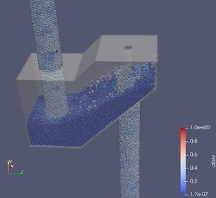
DEM simulation & granular-material modeling
Model particle-machine interaction in systems handling regolith, powders, soil, aggregates, and bulk solids, evaluating flow behavior, torque loading, jamming risk, material buildup, throughput, contact forces, and wear-prone regions.
- Lunar regolith & ISRU handling systems
- Augers, conveyors, hoppers, and feed systems
- Excavation and wheel\u2013soil interaction
- Bulk-solid transport and processing equipment
- Design trade studies and parameter sweeps
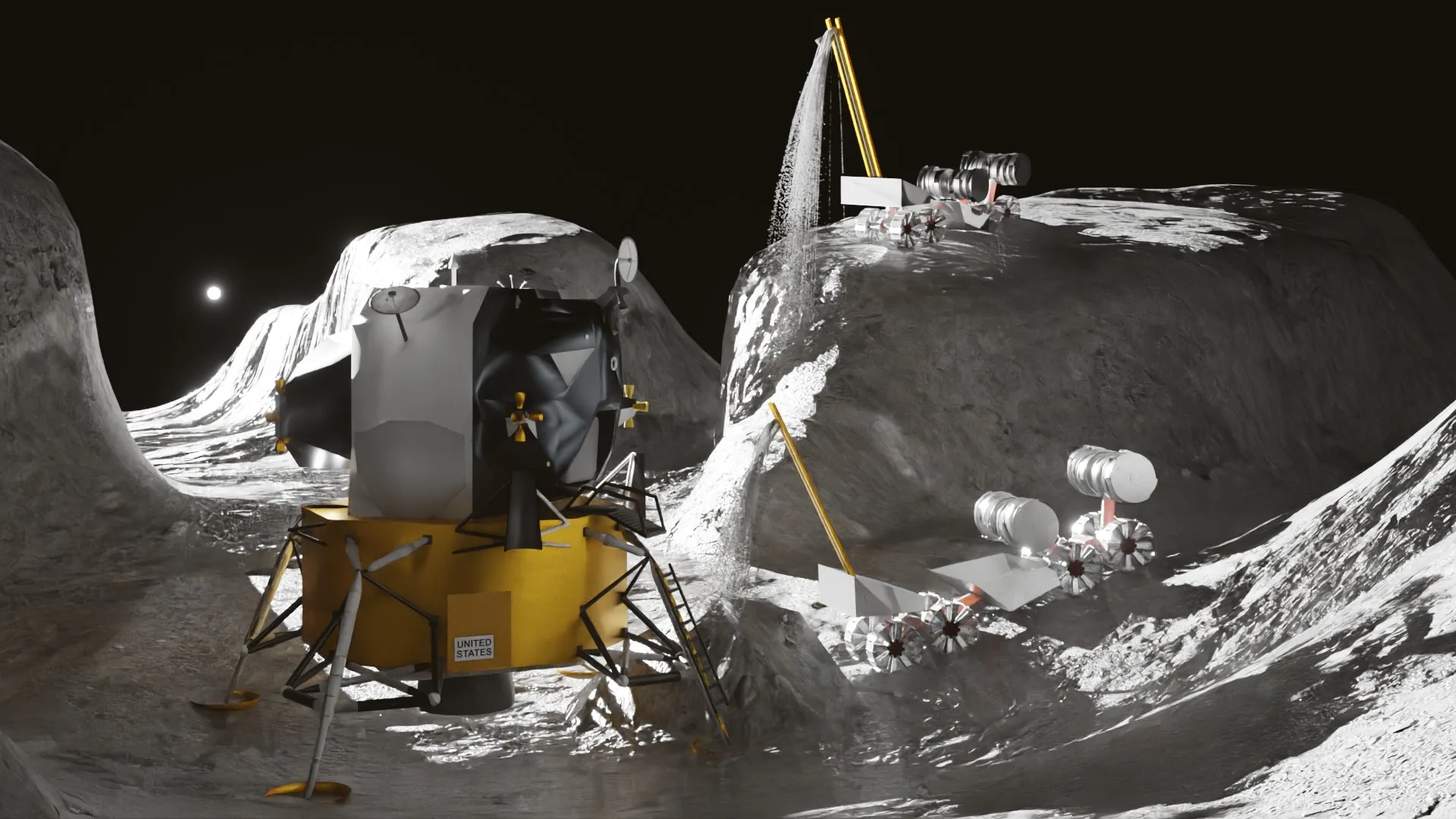
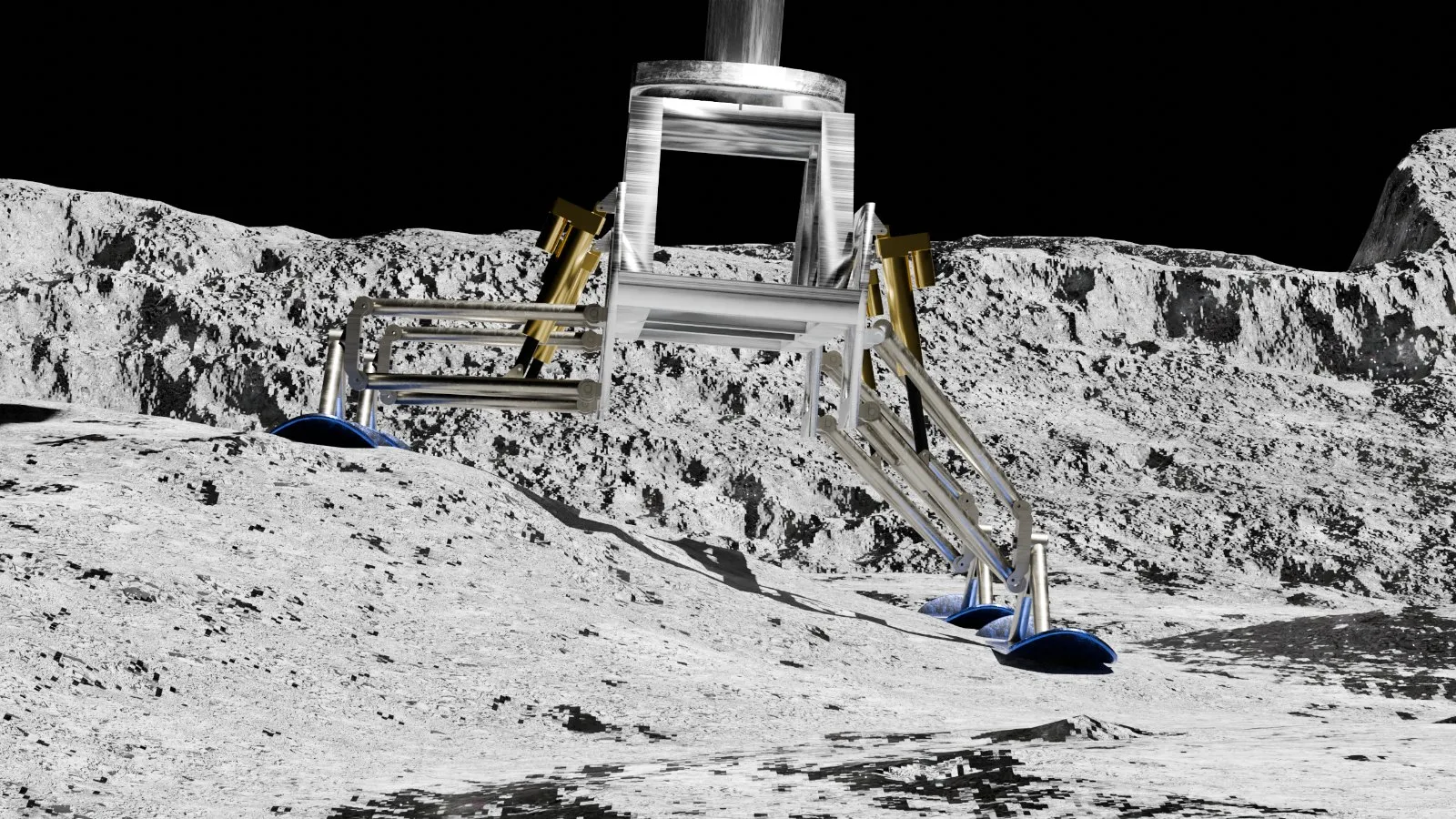
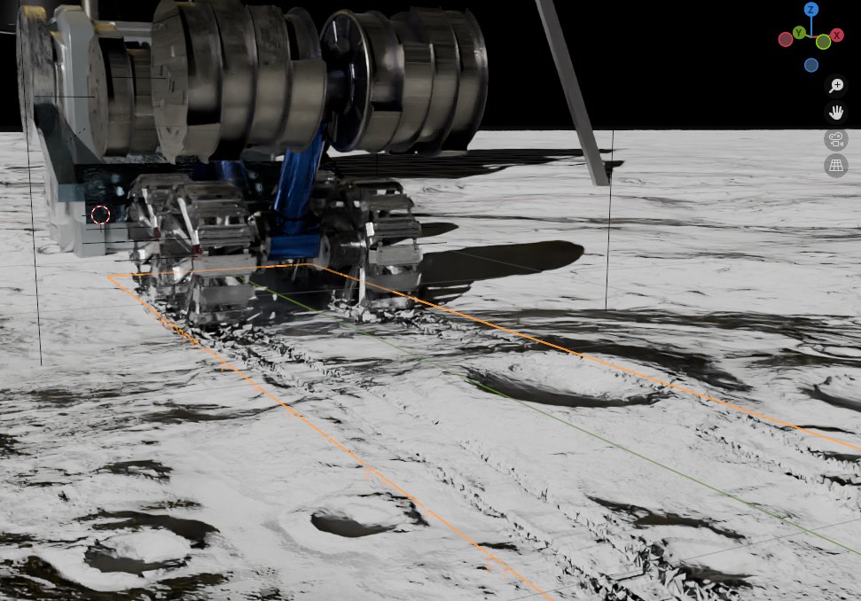
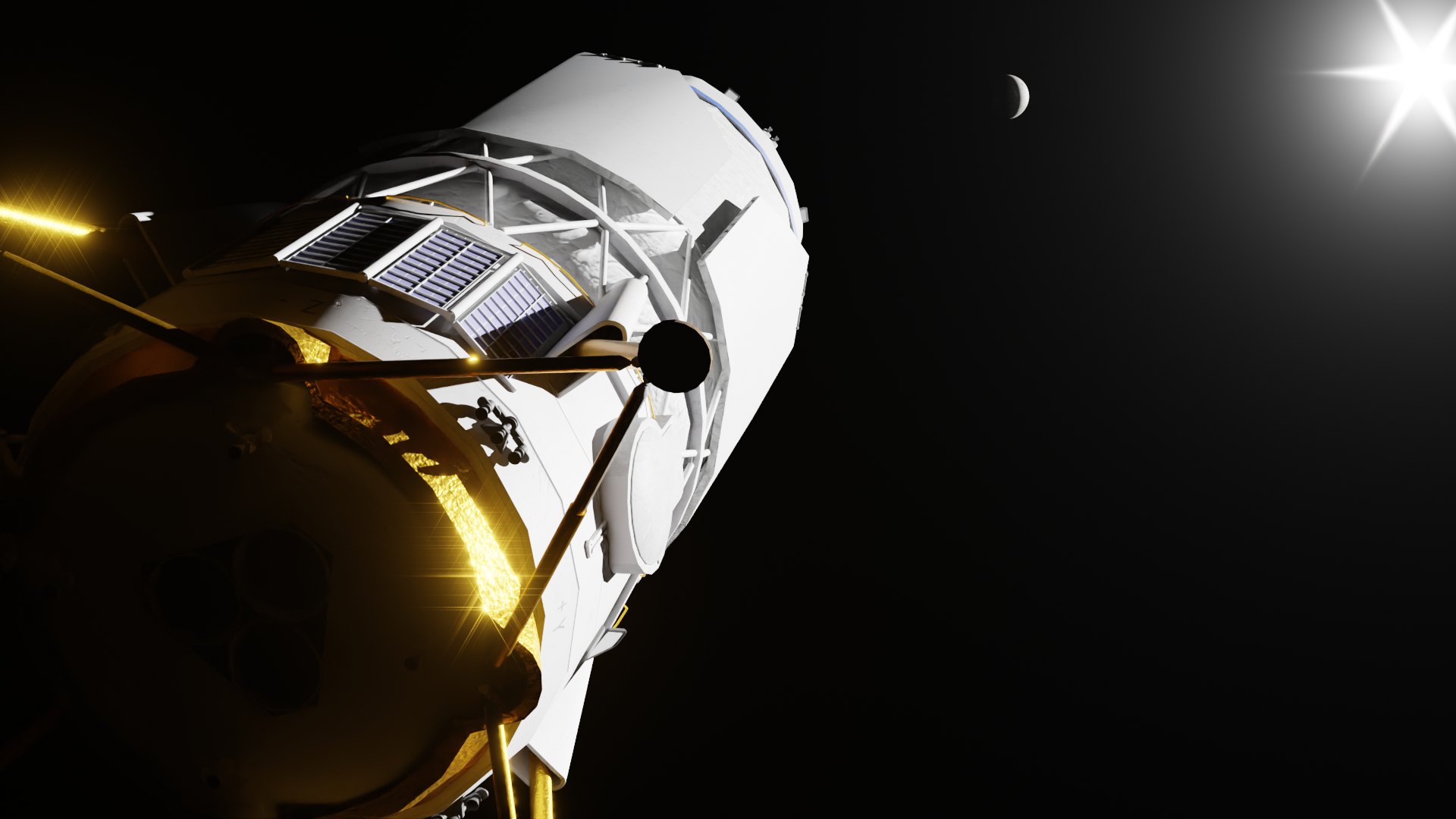
3D technical visualization & animation
Build high-quality visual assets from CAD models, Blender, Unreal Engine, animation, and simulation-informed scenes to demonstrate system function, interfaces, mission operations, and hardware concepts.
- Proposal and pitch-deck visuals
- Blender renders & Unreal Engine mission environments
- Mechanism operation & integration animations
- Lander, rover, drone, and ISRU system visualizations
- Customer, investor, NASA, and DoD briefing graphics
We don't make visuals that are disconnected from the hardware. AeroFly builds on real CAD geometry, simulation outputs, mechanical-design knowledge, and mission context, so every visual is technically grounded and easy for stakeholders to understand.
- DEM simulation results and engineering summaries
- Force, torque, throughput, and contact-load estimates
- Particle flow, buildup, and jamming visualizations
- High-quality renders and technical graphics
- Mechanism and mission-operation animations
- Interface and integration visualizations
- Proposal, pitch, and briefing-ready visual assets
Need to simulate, visualize, or explain a complex hardware system?
We turn complex engineering concepts into clear analysis, high-quality visuals, and decision-ready technical communication.
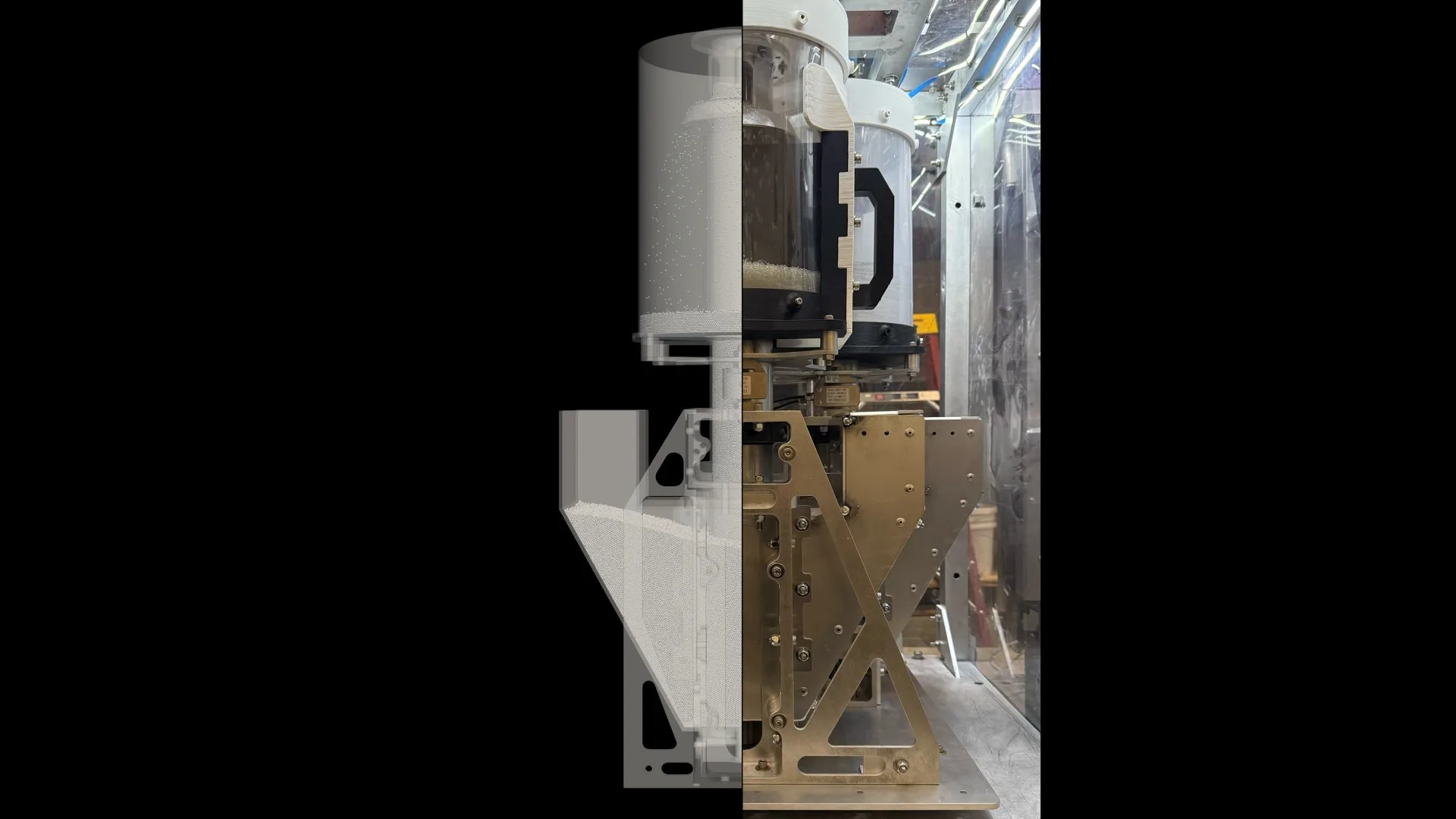
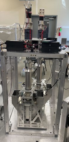
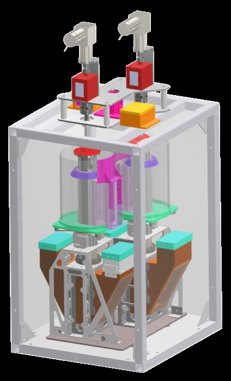
Physics-based models, validated against hardware.
Three disciplines, one accountable team: from granular-flow simulation to manufacturing-ready drawings.
Discrete-element modeling
We simulate millions of regolith grains in Project Chrono's DEM-Engine to predict flow, torque, and power draw, the models that underpin Rego-LIFT's NASA Phase II.
Project Chrono · DEM-Engine Discuss a DEM study →Multiphysics analysis & FEA
A full multiphysics toolset spanning static and transient structural, explicit dynamics, thermal, modal, and topology optimization, applied across mechanisms, structures, and systems to de-risk designs and strip mass while holding margins under real-world loads.
Multiphysics · FEA · explicit dynamics Request an analysis →Manufacturing-ready CAD
Detailed CAD models, assemblies, and drawings with precise GD&T and fit verification. Analysis that lands as hardware you can actually build.
Manufacturing-ready · GD&T Request a quote →Two domains, one modeling discipline.
Physics-based twins for space hardware, and high-fidelity as-built twins for ground infrastructure.
As-built digital twins of live industrial facilities.
Working with reality-capture partners who document complex operating facilities in service, AeroFly turns the resulting point-cloud data into survey-grade as-built 3D models — so owners and engineering teams can plan, maintain, and upgrade against the asset exactly as it stands today, not as it was drawn.
Tap a marker to explore the chamber setup.
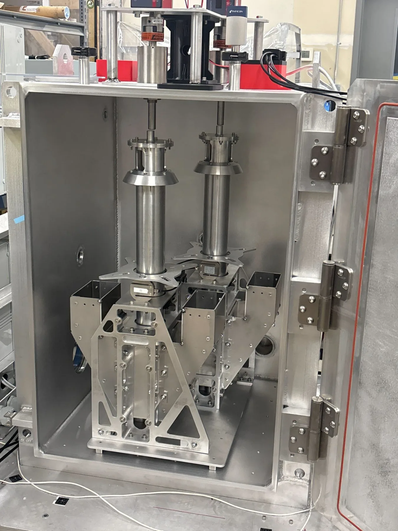
Rotary feedthroughs
Two rotary feedthroughs transmit torque and sensor signals through the chamber wall without breaking vacuum, driving the moving mechanism inside while keeping the seal intact.
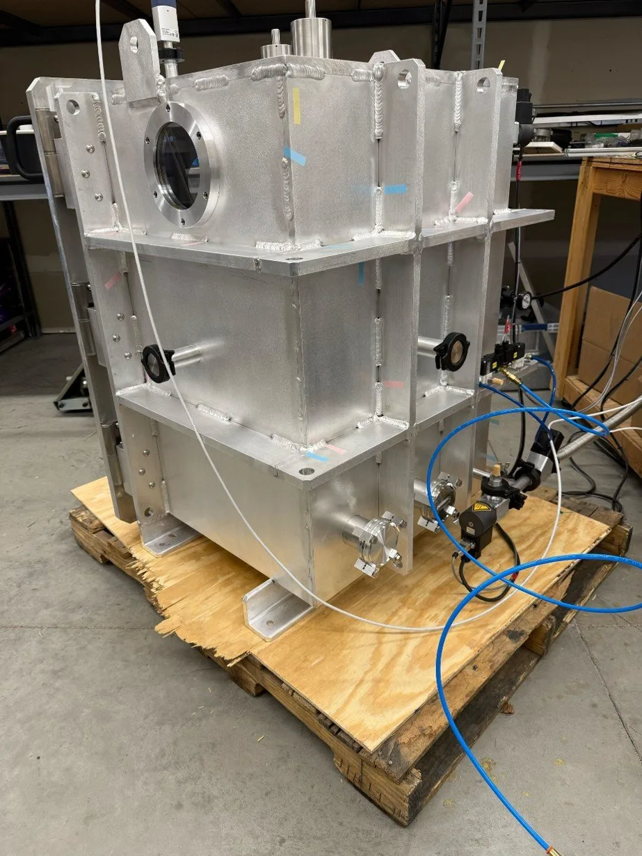
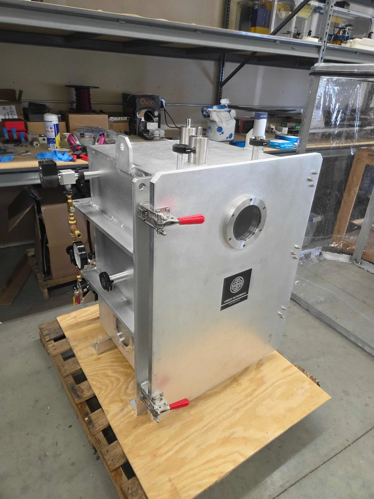
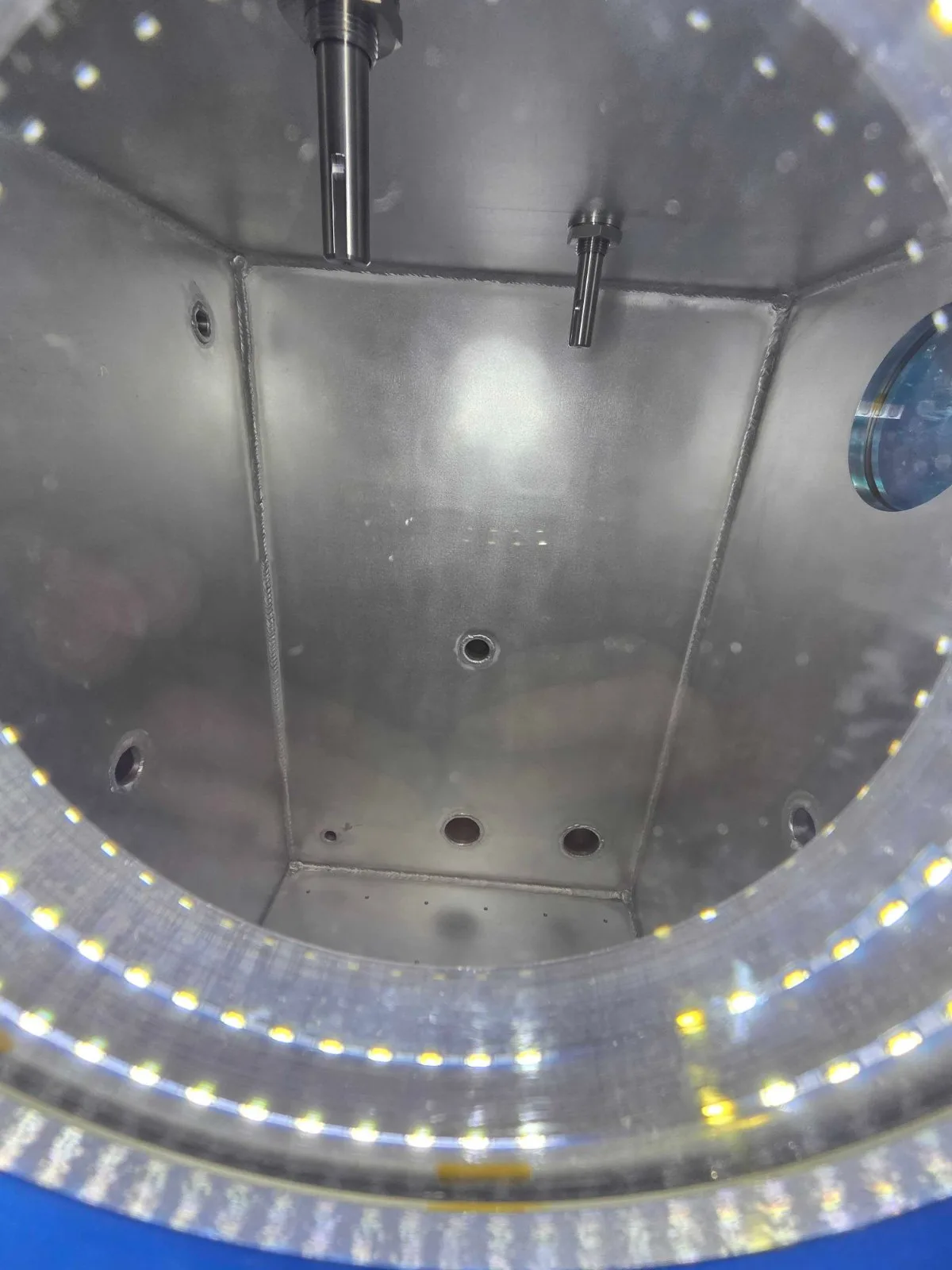
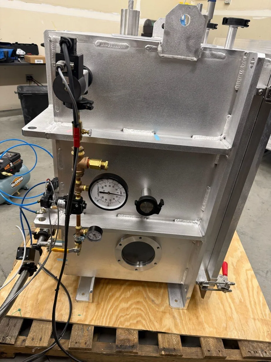
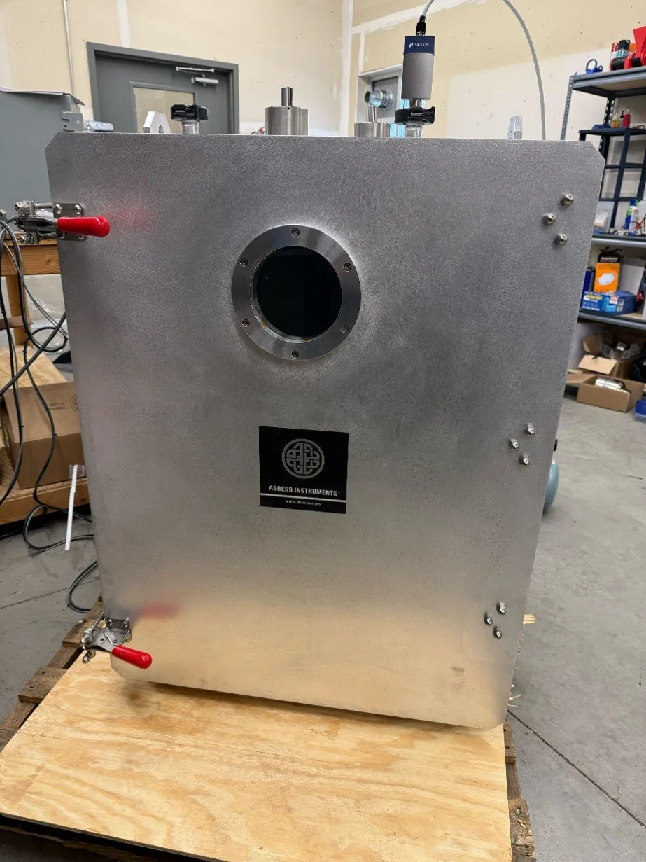
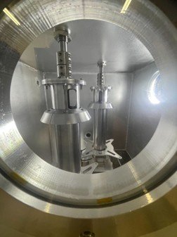
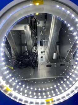
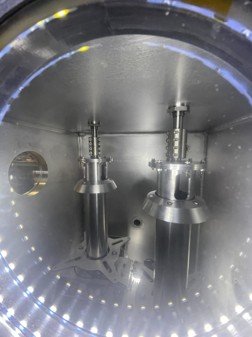
- Pump down to a sub-micron base pressure (~1×10⁻⁴ Torr) and hold it
- Log and export chamber pressure in real time (Inficon gauges, Watlow control)
- Drive rotary mechanisms under vacuum through the feedthroughs
- Measure torque, axial load, and power draw on the test article
- Monitor visually through three internally-lit 5″ Clearview viewports
- Pass 25 sensor channels through the wall via a Sub-D feedthrough
- Controlled gas purge and venting between runs
| Chamber | 24 × 24 × 36 in · AL 6061-T6 |
|---|---|
| Base pressure | ~1 × 10⁻⁴ Torr (sub-micron) |
| Pump | Welch DuoSeal 1397 · two-stage rotary vane |
| Feedthroughs | 2× rotary (SS-750-SLAE) + 25-pin Sub-D |
| Instrumentation | Inficon PCG550 + CVM-201 · logging / export |
| Viewports | 3× 5″ Clearview, internally lit |
|---|---|
| Fixturing | 34× ¼-20 mounting points |
| Ports | 2× QF40 · LF63 · QF25 · 25-pin Sub-D |
| Venting | Gas-purge kit · controlled vent manifold |
| Control | Watlow controller · control box |
|---|---|
| Construction | Welded AL 6061-T6 · #4 finish |
| Weight | Chamber 435 lb · full system 630 lb |
| System size | 37 × 34 × 47 in (W×D×H) |
An adversarial read before you submit.
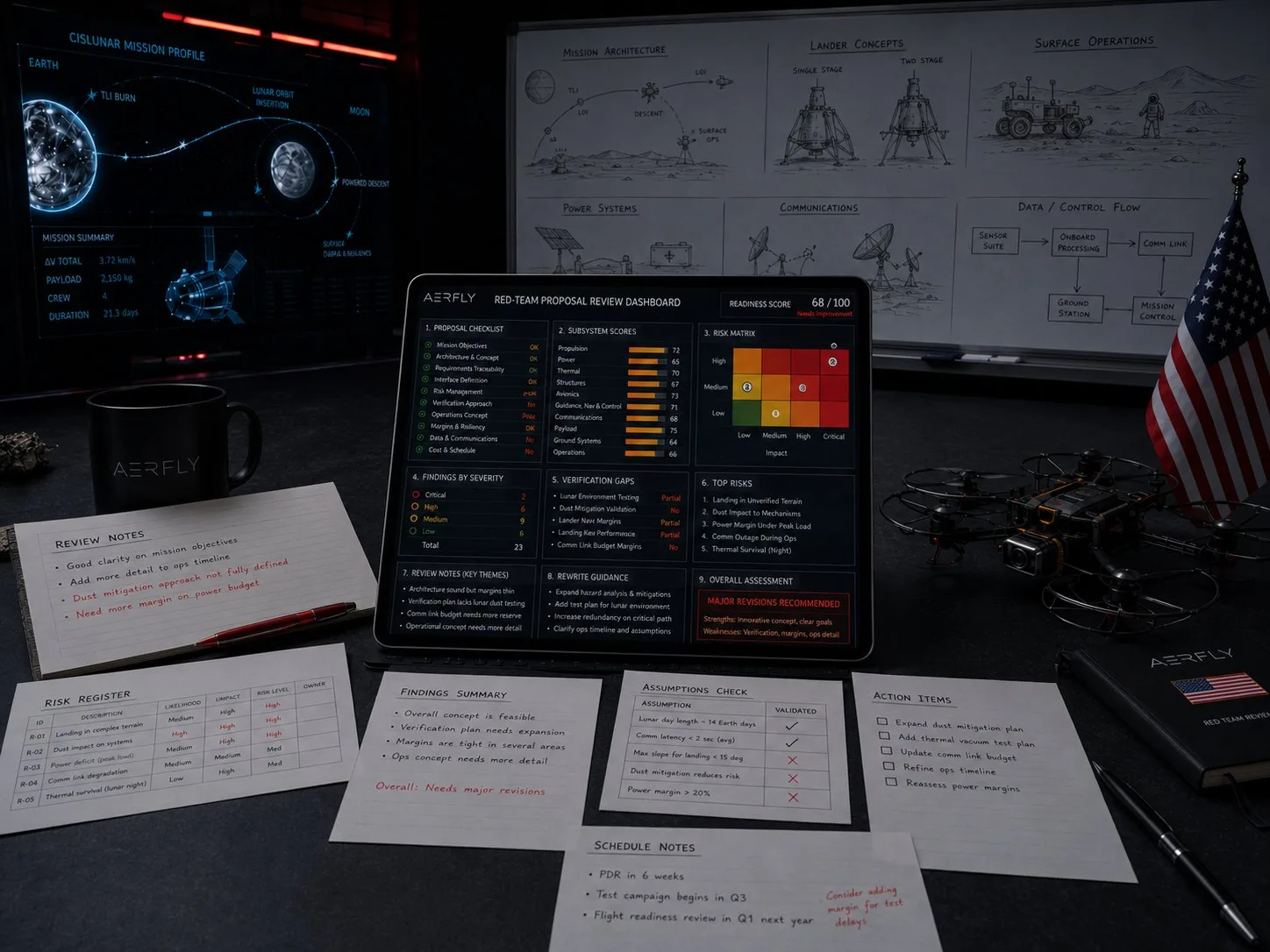 Red-team review · technical volume
Red team proposal review
Independent, adversarial review of your technical proposal before it goes out the door. Our NASA-funded engineers pressure-test the approach, technical volume, and risk posture, the same rigor that won AeroFly's own back-to-back NASA SBIRs.
| Scope | Approach · technical volume · risk |
|---|---|
| Format | Red / gold color-team reviews |
| Output | Scored findings & rewrite guidance |